2D Mapping Bot
Aim
To create a bot which maps a 2D top view of the floor, plotting all the obstacles and boundaries of the area.
Components List
- Arduino IDE
- HC05 Bluetooth Module
- 28-BYJ-48 Stepper Motor (2)
- ULN2003 Stepper Driver (2)
- SG90 Micro Servo
- HCSR04 Ultrasonic Sensor
- 9V Battery
- 6V Battery
- Breadboard (small)
- Switch
- Jumper Wires
- Zip Ties
- Chassis (Metal Body, Wheels)
Working
The 2D mapping bot has been designed and programmed to be controlled by the user in terms of locomotion. The working can be classified into two major processes: Locomotion and Scanning.
Locomotion
The HC05 Bluetooth module is utilised for communication purpose to move the bot throughout the workspace. The stepper motors used are the 28-BYJ-48 model which are to be used along with the ULN2003 stepper driver for each. The stepper motors are utilised to ensure fixed movement of the bot, i.e. a fixed distance each time a command is passed to it, to ensure a proper scaled plotting of the workspace. Locomotion is controlled by connecting the module to the PC and clicking the arrow keys on the keyboard after opening the Processing IDE.
Scanning
Scanning is done by the HCSR04 ultrasonic sensor mounted upon an SG90 servo motor which rotates from 0 to 180 degrees back and forth. Scanning is done by sending pulses of ultrasonic waves for each angular position of the sensor. Scanning goes on continuously as long as the bot is switched on. It comes to a halt only when the bot receives a command to perform a particular locomotive action. As soon as that action is completed, scanning resumes.
Results
Detailed Documentation:
Components Pins Description
ULN 2003 Stepper Driver
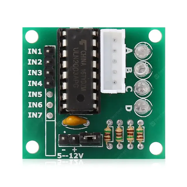
It is the motor driver generally used with steppers. Each 28BYJ-48 stepper needs one ULN2003 stepper driver to run. - IN1,IN2,IN3,IN4 - Connected to the Arduino and receive signals from the microcontroller.
- 5-12V - Power supply to the driver. - 5 Pins in the White casing - Connected to the stepper motor. Datasheet of the Component.
28BYJ-48 Stepper Motor

It is a unipolar 5 wired stepper motor, where all the 5 wires are connected to the 5 output pins of the ULN2003 stepper driver. Motor specs can be found in the datasheet.
SG90 Micro Servo
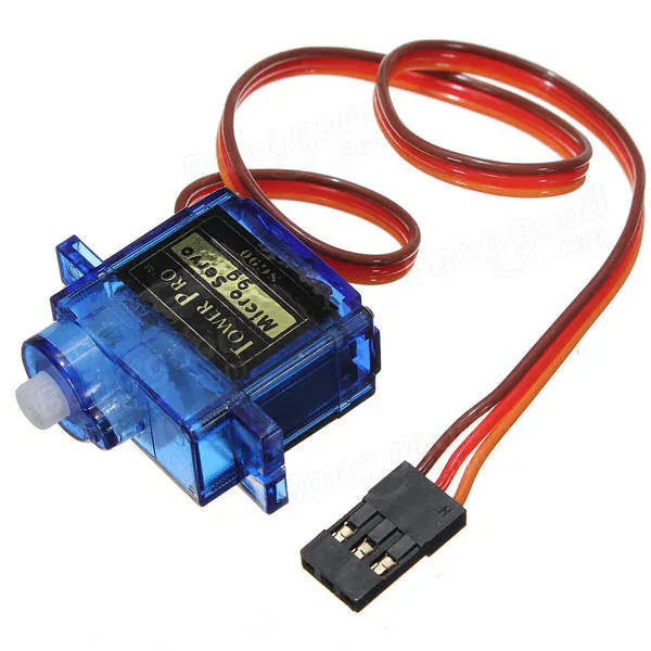
It is a micro servo motor which can rotate from 0 to 180 degrees. The pins description is as follows:
- Yellow - Connected to a digital OUTPUT pin. Servo is rotated by giving the angular position using digitalWrite on this pin.
- Red - Connected to +5V Power supply.
- Brown - Connected to ground. Data sheet.
HCSR04 Ultrasonic Sensor
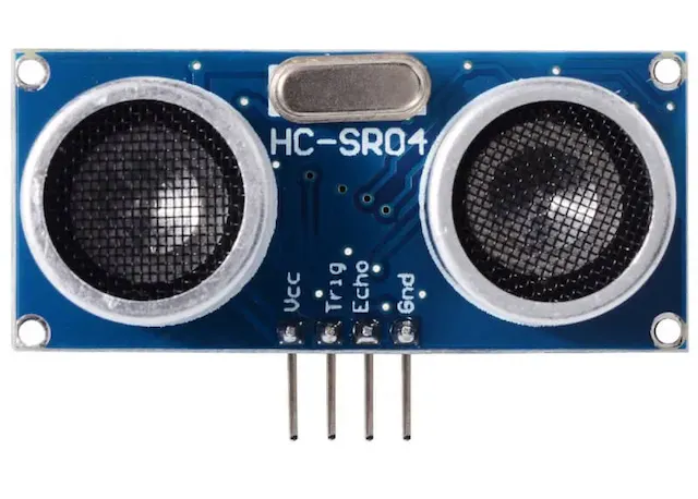
- VCC - Connected to +5V Power supply.
- Trig - It is an OUTPUT pin connected to a Digital pin. Sends out UV pulses for distance calculation.
- Echo - It is an INPUT pin connected to a Digital pin. Receives sent out UV pulses and is used along with pulseIn to calculate pingTravelTime.
- GND - Connected to ground. Datasheet.
HC05 Bluetooth Module
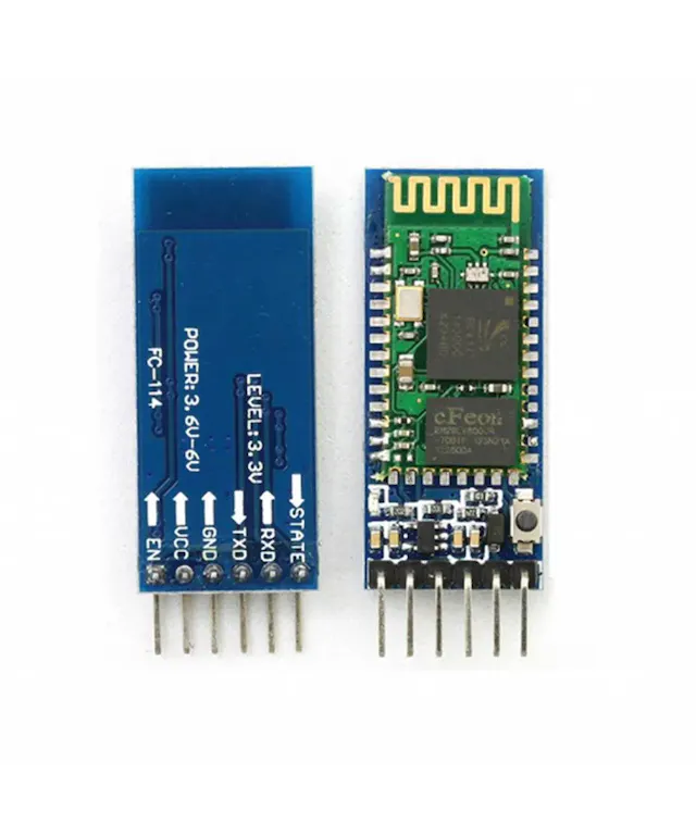
- VCC - Connected to +5V supply.
- GND - Connected to ground.
- TXD - Connected to RX of the Arduino. Transmitter: Transmits data received via Bluetooth as serial data.
- RXD - Connected to TX of the Arduino. Receiver: Receives serial data and sends it via Bluetooth. Datasheet of HC05 module.
Connections Schematic
The schematic below shows the circuit connections of the bot:
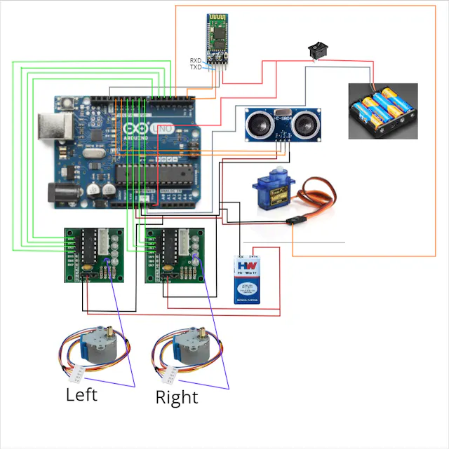
Power Supply
6V Supply The connections to the 6V power supply are:
- +ve : HC05 Bluetooth module, Switch, Vin of Arduino.
-ve : GND of Arduino. 9V Supply Connections to 9V power supply:
- +ve : +ve of each ULN2003 Stepper driver.
- -ve : -ve of each ULN2003 Stepper driver, GND of SG90 servo, GND of HCSR04 sensor, GND of Arduino.
Arduino IDE Code
1. #include<Servo.h>
2. #include <Stepper.h>
3. #define STEPS 2038 // the number of steps in one revolution of your motor (28BYJ-48)
4.
5. Stepper stepperR(STEPS, 8, 10, 9, 11);
6. Stepper stepperL(STEPS, 4, 6, 5, 7);
7. Servo Myservo;
8. int i=1;
9. int n;
10. int pos=0,k=0;
11. volatile char inputByte;
12. unsigned long pingTravelTime;
13. int trigPin=12;
14. int echoPin=13;
15. const int interruptPin = 2; // (optional)an led can be connected to check the shift in command execution
16.
17. void setup() {
18.   // put your setup code here, to run once:
19.   Serial.begin(9600);
20.   Myservo.attach(3);
21.   pinMode(2,OUTPUT);
22.   pinMode(trigPin,OUTPUT);
23.   pinMode(echoPin,INPUT);
24.   pinMode(4,OUTPUT);
25.   pinMode(5,OUTPUT);
26.   pinMode(6,OUTPUT);
27.   pinMode(7,OUTPUT);
28.   pinMode(8,OUTPUT);
29.   pinMode(9,OUTPUT);
30.   pinMode(10,OUTPUT);
31.   pinMode(11,OUTPUT);
32.
33.   digitalWrite(interruptPin,HIGH);
34. }
35.
36. void loop() {
37.   // put your main code here, to run repeatedly:
38.   Myservo.write(pos);
39.   delay(10);
40.   digitalWrite(trigPin,LOW);
41.   delayMicroseconds(10);
42.   digitalWrite(trigPin,HIGH);
43.   delayMicroseconds(10);
44.   digitalWrite(trigPin,LOW);
45.   pingTravelTime=pulseIn(echoPin,HIGH);
46.   if(Serial.available()>0) {
47.     inputByte= Serial.read();
48.     digitalWrite(interruptPin,LOW);
49.     command();
50.     digitalWrite(4,LOW);
51.     digitalWrite(5,LOW);
52.     digitalWrite(6,LOW);
53.     digitalWrite(7,LOW);
54.     digitalWrite(8,LOW);
55.     digitalWrite(9,LOW);
56.     digitalWrite(10,LOW);
57.     digitalWrite(11,LOW);
58.   }
59.   else {
60.     digitalWrite(interruptPin,HIGH);
61.   }
62.   Serial.print(pos);
63.   Serial.print(',');
64.   Serial.print(pingTravelTime);
65.   Serial.print('.');
66.   if (pos==180)
67.   i=-1;
68.   if (pos==0)
69.   i=1;
70.   pos =pos+i;
71. }
72. void command() {
73.   if(inputByte=='F') {
74.       for(n=0;n<=1024;n++) {
75.       stepperR.setSpeed(10);
76.       stepperR.step(2);
77.       stepperL.setSpeed(10);
78.       stepperL.step(2);
79.       }
80.
81.   }
82.   if(inputByte=='R') {
83.     for(n=0;n<=1200;n++) {
84.     stepperL.setSpeed(10);
85.     stepperL.step(1);
86.     stepperR.setSpeed(10);
87.     stepperR.step(-1);
88.     }
89.   }
90.   if(inputByte=='L') {
91.     for(n=0;n<=1200;n++) {
92.     stepperL.setSpeed(10);
93.     stepperL.step(-1);
94.     stepperR.setSpeed(10);
95.     stepperR.step(1);
96.     }
97.   }
98.   if(inputByte=='B') {
99.       for(n=0;n<=1024;n++) {
100.       stepperR.setSpeed(10);
101.       stepperR.step(-2);
102.       stepperL.setSpeed(10);
103.       stepperL.step(-2);
104.       }
105.   }
106. }
The above code is written in Arduino IDE, where the code is related to the physical working of the bot, both Scanning and Locomotion.
Explanation: The libraries included are Servo.h for the SG90 servo and Stepper.h for the 28BYJ-48 steppers to function.
- line 5,6 : Initialising the steppers with the total no.of steps and the input pins connected to the digital I/O pins. Stepper name_stepper (noOfSteps,IN1,IN3,IN2,IN4); is the syntax to initialise a stepper.
- line 7 : Initialising the servo.
- line 8 to 14 : initialising many required parameters.
- line 15 : using a digital I/O pin connection for debugging purposes.
- line 20 : declaring the pin connection to the servo.
- line 21 to 31 : declaring the pinMode of all the required pins.
- line 38 : sending angular position to the servo.
- line 40 to 44 : sending out a ultrasonic pulse for obstacle detection.
- line 45 : measuring the ping travel time by using pulseIn() on the echo pin. The time period as long as the echo pin is high, is equal to the time required for the ping(pulse) to travel to the obstacle and reflect back to the receiver.
- line 46 to 61 - checking for any command received in the serial port.
If a command is received:
- line 47 : reading the command and storing it in a variable.
- line 49 : call the function command()
- Jump to line 72 :
- line 73 : checking if the command is F(forward). If yes:
- line 74 : a for loop with 1024 iterations, just for having an arbitrary fixed distance every time the command is given.
Stepper.setSpeed(rpm)is a command for setting speed of the motor in RPM.Stepper.step(stepsPerRevolution)gives the number of steps needed to perform to complete one revolution. - line 75 to 78 : setting the speed of both the steppers to 10 rpm and the steps for each revolution as 2.
- line 82 : checking if the command is R(right). If yes:
- line 83 : a for loop with 1200 iterations, just for having an arbitrarily fixed time required to turn every time the command is given.
- line 84 to 87 : setting the speed of both the steppers to 10 rpm and the steps for each revolution for left stepper as 1, for right stepper as -1(rotates in reverse direction).
- line 90 : checking if the command is L(left). If yes:
- line 91 : a for loop with 1200 iterations, just for having an arbitrarily fixed time required to turn every time the command is given.
- line 92 to 95 : setting the speed of both the steppers to 10 rpm and the steps for each revolution for right stepper as 1, for left stepper as -1(rotates in reverse direction).
- line 98 : checking if the command is B(backward). If yes:
- line 99 : a for loop with 1024 iterations, just for having an arbitrarily fixed distance every time the command is given.
- line 100 to 103 : setting the speed of both the steppers to 10 rpm and the steps for each revolution as -2(reverse direction).
else: Back to line 50 :
- line 50 to 57 : making the input values for both the motors as low so as to switch off the stepper motors, allowing further execution of void loop().
Coming out of the if-else condition :
- line 62 to 65 : printing the angular position and pingTraveltime in the required format to be used in the Processing IDE. This input will be utilised for mapping the scanned area.
- line 66 to 69 : checking for the position to be 0 or 180, depending upon which the addition factor needs to be altered. When the servo is at 0, its position needs to be incremented by 1 for each iteration, to go from 0 to 180, so i= 1. When the servo is at 180, its position needs to be decremented by 1 for each iteration, to go from 180 to 0, so i= -1.
- line 70 : changing the value of the angular position of the servo to be sent as an input for the next iteration. Since i is a global variable, we can utilise void loop() itself for iterations to change servo position gradually.
Debugging option:
To check for proper change in command control from Scanning to Locomotion and vice-versa, it is recommended to use an LED (as we did in our case) to check if the code is executed as expected when commands are received and after they are executed. This process might help since steppers can be a little tricky to deal with and narrowing down the possible reasons for the occuring error would be helpful.
- line 33 : giving the initial input as HIGH, so if an LED is used, its natural state would be HIGH.
- line 48 : when a command is received, the LED is coded to change to LOW state, indicating proper execution of command shift.
- line 60 : as soon as the command execution is done, or if there is no command reception detected for the particular iteration of void loop(), the LED would be in HIGH state.
Processing IDE Code
Now we will explain the processing part.
Introduction
For processing the data, that we receive from Arduino, into a graphical format, we use Processing IDE for this situation. The Processing IDE works for a computer like the Arduino IDE works for a micro-controller. The Processing IDE is similar to Arduino in terms of structure. It has setup functions and draw functions like an Arduino has a setup and loop function. The Processing IDE can communicate with the Arduino IDE through serial communication. This way, we can send data from the Arduino to the Processing IDE and also from the Processing IDE to the Arduino.
Graphical Format
Our Processing Output looked like this :-
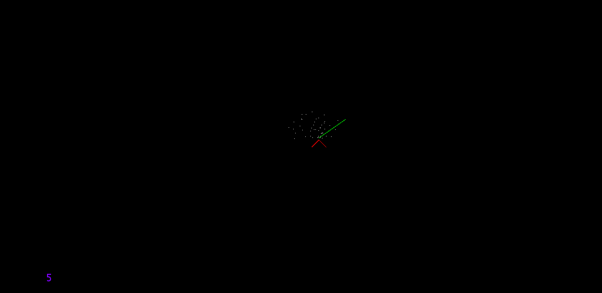
Where,
- That Red Arrow represents our bot.
- The Green Line represents the direction of the Ultrasonic Sensor.
- The White Dots represents obstacle detected.
- The Purple Number at Bottom-RIght corner represents the time taken for completing
draw()loop in processing.
Code
We are going to receive 2 datas from Arduino using bluetooth module which is being used in slave mode :- Sensor Current Angle and Time of Echo pin being high in Ultrasonic Sensor In Processing IDE, the window we are going to generate will be size of 1280×640 pixels and that windows will be supposed to cover 20×10 meters square of area, that means 1280 pixels will be equivalent to 20 meters and same with 640 pixels to 10 meters, which basically means 1 meters = 64 pixels The bot is only going to scan when it is steady. When we command to move using any arrow key, it will stop scanning and start moving, in case of forward and backward, it will move 21 cm at a time, and in case of rotating, it will rotate at an angle of 90°. Now we will explain the processing code part-by-part. For refrence of these commands, visit this site
1) Import and Variable Declaring Part :-
import processing.serial.*; // imports library for serial communication
import java.awt.event.KeyEvent; // imports library for reading the data from the serial port
import java.io.IOException;
Serial myPort;
float roboX, roboY, sensorAngle=0, distance, smr=64, roboSpeed=0, roboAngularVel=0;
float roboAngle=0;
float ot=0, nt=0, i=1, j=1, l=20;
int pixel1[][]=new int[1280][640];
long iTime;
int iAngle = 0;
int first=1,second=1;

int move_time=6150, flag=0, flag2=0, nt_move, ot_move, rotate_time=3500;
In this code, the import part imports library for serial communication and for reading the data from the serial port. Now, in variables part,
roboXandroboYare x and y coordinates of the bot in the windows (Note that origin in windows is considered at top left corner and moving left will let increase in x value, moving down will let increase in y value)sensorAngleis the current angle of sensor in processingdistanceis just distance calculated using the ping time receivedroboSpeed&roboAngularVelare speed and angular velocity of the bot when it is movingroboAngleis the current angle of bot in processingpixel1is array consiting of 1280×640 elements which is going to store the data of obstacle found, like if obstacle is found at some coordinate in terms of pixel, we will change the element ofpixel1into ‘1’ which address match with the cordinates.iTime and iAngleis inputs received from Arduino using Serial Communicationmove_time&rotate_timeis time taken for the bot to move and rotate respectivelymyPortis an object created for sending and receiving data using the serial communication protocol- Rest other variables are for logic implementation which will be explained later in this documentation
2) void setup() part :-
void setup()
{
  size(1280,640,P2D);
  background(0,0,0);
  myPort = new Serial(this,"COM11", 9600); // starts the serial communication
  myPort.bufferUntil('.');
  roboX = width/2.0;
  roboY = height/2.0;
  for (int i=0;i<1280;i++)
  for (int j=0;j<640;j++)
  pixel1[i][j]=0;
  ot=millis();
}
This is void setup(), a built-in function in processing which will run only for one time at start.
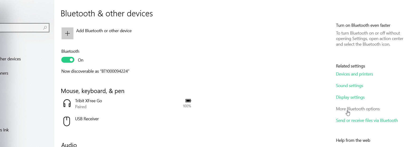
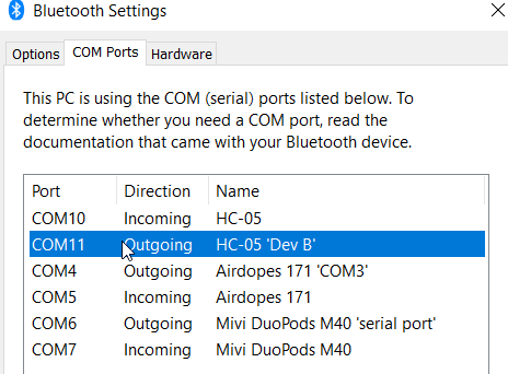
size(1280,640,P2D);command is for setting size of window screen. The 1280,640 number inside the bracket explains the width and height of the window. The ‘P2D’ sets the type of screen renderer. The P2D renderer is an alternative 2D renderer that is substantially faster than the default renderer for most tasks, but it sacrifices some visual quality for speed.background(0,0,0);sets the background to black, the “0,0,0” represents R,G,B value.myPort = new Serial(this,"COM11", 9600);starts the serial communication with “COM11”. In my case, HC-05, i.e, the bluetooth module, established connection with my laptop using COM11.You can check the port by opening the bluetooth settings, at right side, click on
More Bluetooth options
![b389bafd6b467faca7ed65403c64c506.png]()
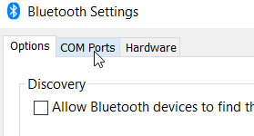
Then go to the COM Ports
![fedd236637eaa8c6bc4bbc0f08cbce5e.png]()
The one with ‘Dev-B’ written is your COM port
![760d7083832c84f6a83aec1acb9130a0.png]()
myPort.bufferUntil('.');reads the data from the serial port up to the character ‘.’. So actually it reads this: ‘angle,time.’. It sets a specific byte to buffer until before callingserialEvent().- The two commands
roboX = width/2.0;&roboY = height/2.0;is for intialising the current position of the bot in the middle of the window. (widht and height are in-built function which represents the widht and height of the window screen) - Next part is 2 for loops and a command
pixel1[i][j]=0;inside it. This part initialises thepixel1array by setting every element to 0 (as 1 was for objects) ot=millis();set the intial time forroboMove()function.
3) void drawRobot() part :-
void drawRobot()
{
  stroke(255,0,0);
  line(roboX, roboY, roboX + (l*cos(radians(45+roboAngle))), roboY + (l*sin(radians(45+roboAngle))));
  line(roboX, roboY, roboX - (l*cos(radians(45-roboAngle))), roboY + (l*sin(radians(45-roboAngle))));
}
This function is use for drawing body of the bot each time when the draw() functions loops each time

stroke(255,0,0);sets the color of line or any shape to be drawn.- The 2
line()command draws the left and right line shown in the figure
4) void drawLine() part :-
1. void drawLine()
2. {
3.   float x=roboX+3.84*(sin(radians(roboAngle)));
4.   float y=roboY-3.84*(cos(radians(roboAngle)));
5.   stroke(0,255,0);
6.   line(x, y, x+(smr*cos(radians(roboAngle-sensorAngle))), y+(smr*sin(radians(roboAngle-sensorAngle))));
7. }
In this part, we are drawing line which will represent the sensor direction.
- In Line 3 & 4, as mentioned earlier, the ultrasonic sensor is located 6 cm away from centre, that’s why we are changing the one end coordinate of line
- Rest is code for drawing the line in green color

5) void drawObstacle() part :-
1. void drawObstacle()
2. {
3.   distance = iTime * 0.034 / 2.0;
4.   distance = distance * 0.64;
5.   int i1;
6.   int j1;
7.   float x=roboX+3.84*(sin(radians(roboAngle)));
8.   float y=roboY-3.84*(cos(radians(roboAngle)));
9.   i1=int(x+(distance*cos(radians(roboAngle-sensorAngle))));
10.   j1=int(y+(distance*sin(radians(roboAngle-sensorAngle))));
11.   if ((second==1)&&(first==1))
12.   if ((distance<smr)&&(((i1>0)&&(i1<1280))&&((j1>0)&&(j1<640))))
13.   pixel1[i1][j1]=1;
14.   loadPixels();
15.   for (int i=0;i<1280;i++)
16.   for (int j=0;j<640;j++)
17.   if (pixel1[i][j]==1)
18.   {
19.     int a = 1280*j+i;
20.     pixels[a]=color(255,255,255);
21.   }
22.   updatePixels();
23. }
This part of code is about designing a function which will draw obstacle every time as the draw() loops everytime.
- At Line 3, distance is being calculated using the ping time received and stored in
distancevariable - At Line 4, value in the
distancevariable is converted from meters to pixels - At Line 6 & 7, as ultrasonic sensor is located 6cm (=3.84 pixels) far from robot, the new coordinates of the sensor with repsect to the bot coordinates is being calculated.
- At Line 9 & 10, we are calculating coordinates of the object detected with respect to direction of sensor and the bot, and storing it to 2 variables
- From Line 11 to 13, we are marking the obstacle in the array
pixel1. Note that inifpart, we are restricting distance which is greater thansmrto minimise the error. - From Line 14 to 22, we are updating the picture of
pixel1into the screen

6) void roboMove() part :-
1. void roboMove()
2. {
3.   nt=millis();
4.   float len1=(nt-ot)*roboSpeed;
5.   roboX=roboX+(len1*sin(radians(roboAngle)));
6.   roboY=roboY-(len1*cos(radians(roboAngle)));
7.   roboAngle=roboAngle+((nt-ot)*roboAngularVel);
8.   ot=nt;
9. }
In this part, we define a function which detemines the position of the bot based on the current speed of the bot and time spent in the code so even if it takes too much times at a moment, it will show it at constant pace. The reason why I intialised the variable ot with millis() is because if we keep ot = 0, and if it takes too much time in executing the size(1280,640,P2D); command, and given that the speed of bot is high from the start, it will could leave the window screen, so I thought it will be best if we initialise ot only when the simulation begins.
7) void values_update() part :-
void values_update()
{
  roboMove();
  sensorAngle=iAngle;
}
This function basically combines all command for updating value everytime
8) void keyPressed() part :-
1. void keyPressed()
2. {
3.   if ((key==CODED)&&(flag==0))
4.   {
5.     if (keyCode==UP)
6.     {
7.      myPort.write('F');
8.      roboSpeed=0.00218;
9.      flag=1;
10.     }
11.     if (keyCode==DOWN)
12.     {
13.       roboSpeed=-0.00218;
14.       flag=1;
15.       myPort.write('B');
16.     }
17.     if (keyCode==RIGHT)
18.     {
19.       myPort.write('R');
20.       roboAngularVel=0.0257;
21.       flag=2;
22.     }
23.     if (keyCode==LEFT)
24.     {
25.       roboAngularVel=-0.0257;
26.       myPort.write('L');
27.       flag=2;
28.     }
29.     first=0;
30.     second=0;
31.   }
32. }
This function is automatically called whenever a key is pressed. key is inbuilt variable which will store the ASCII data of key pressed. If the key pressed belongs to UP, DOWN, LEFT, RIGHT, or any non-ASCII key, it will pass the line 3, if(key==CODED). So you need to check another in-built variable, keyCode, which tells the non-ASCII key pressed. If UP or DOWN key is pressed, then it will assign the variable roboSpeed as +0.00218 or -0.00218 respectively If LEFT or RIGHT key is pressed, it will assign the variable roboAngularVel as -0.0257 or +0.0257 respectively Now at last, this function will make the variables first and second as 0. These 2 variables ensures that at void drawObstacle() function, at line if ((second==1)&&(first==1)), it will only allow to draw obstacle if these 2 variables are one. The variable second will become 1 if it passes given amount of time which is the time bot needs to move. The variable first only become 1 when it receives a set of serial data, it ensures that if robot moves at neew position, it will not mark the same data which was given my arduino before.
9) void serialEvent() part :-
void serialEvent(Serial myPort)
{
  String data = myPort.readStringUntil('.');
  data = data.substring(0,data.length()-1);
  int index1 = data.indexOf(",");
  String angle= data.substring(0, index1);
  String time= data.substring(index1+1, data.length());
  iAngle = int(angle);
  iTime = int(time);
  first = 1;
}
As we commanded the processing IDE at void setup() that myPort.bufferUntil('.'), so this processing will be only called when ‘.’ comes in the data. So in this function, as we are sending the data in angle,time. format, so it will divide the serial data string into 2 strings and then it will calculae and store the data into 2 variables, iAngle and iTime And as mentioned earlier, this function will also set the variable first to 1
10) void draw() part :-
1. void draw()
2. {
3.   int nice=millis();
4.   background(0,0,0);
5.   drawObstacle();
6.   drawRobot();
7.   drawLine();
8.   if (flag==1)
9.   {
10.     if (flag2==0)
11.     {
12.       ot_move=millis();
13.       flag2=1;
14.     }
15.     if ((millis()-ot_move)>move_time)
16.     {
17.       flag=0;
18.       roboSpeed=0;
19.       roboAngularVel=0;
20.       flag2=0;
21.       first=1;
22.       second=1;
23.     }
24.   }
25.   if (flag==2)
26.   {
27.     if (flag2==0)
28.     {
29.       ot_move=millis();
30.       flag2=1;
31.     }
32.     if ((millis()-ot_move)>rotate_time)
33.     {
34.       flag=0;
35.       roboSpeed=0;
36.       roboAngularVel=0;
37.       flag2=0;
38.       first=1;
39.       second=1;
40.     }
41.   }
42.   values_update();
43.   int f=millis();
44.   fill(128,0,255);
45.   textSize(20);
46.   text(str(f-nice),100,600);
47. }
This is the main function is going to loop until the program is closed.
- Line 4 is for resetting the background image or the old screen will not be cleared
- Line 5, 6, 7 & 42 is for calling theses function so they could come in action
- As bot is moving or rotating for a period of time, the lines from 8 to 41 takes cares of that, if bot is rotating, flag will be 2, and if bot is moving front or back, flag will be 1.
- Line 3 & from 43 to 46 is for calculating and printing that time taken for completing a loop and to print it at bottom right corner.
Here is the whole code :-
import processing.serial.*; // imports library for serial communication
import java.awt.event.KeyEvent; // imports library for reading the data from the serial port
import java.io.IOException;
Serial myPort;
float roboX, roboY, sensorAngle=0, distance, smr=64, roboSpeed=0, roboAngularVel=0;
float roboAngle=0;
float ot=0, nt=0, i=1, j=1, l=20;
int pixel1[][]=new int[1280][640];
long iTime;
int iAngle = 0;
int first=1,second=1;

int move_time=6150, flag=0, flag2=0, nt_move, ot_move, rotate_time=3500;

void setup()
{
  size(1280,640,P2D);
  background(51);
  stroke(0,0,0);
  myPort = new Serial(this,"COM11", 9600); // starts the serial communication
  myPort.bufferUntil('.');
  roboX = width/2.0;
  roboY = height/2.0;
  for (int i=0;i<1280;i++)
  for (int j=0;j<640;j++)
  pixel1[i][j]=0;
  ot=millis();

}

void draw()
{
  int nice=millis();
  background(0,0,0);
  drawObstacle();
  drawRobot();
  drawLine();
  if (flag==1)
  {
    if (flag2==0)
    {
      ot_move=millis();
      flag2=1;
    }
    if ((millis()-ot_move)>move_time)
    {
      flag=0;
      roboSpeed=0;
      roboAngularVel=0;
      flag2=0;
      first=1;
      second=1;
    }
  }
  if (flag==2)
  {
    if (flag2==0)
    {
      ot_move=millis();
      flag2=1;
    }
    if ((millis()-ot_move)>rotate_time)
    {
      flag=0;
      roboSpeed=0;
      roboAngularVel=0;
      flag2=0;
      first=1;
      second=1;
    }
  }
  values_update();
  int f=millis();
  fill(128,0,255);
  textSize(20);
  text(str(f-nice),100,600);
}

void drawRobot()
{
  stroke(255,0,0);
  line(roboX, roboY, roboX + (l*cos(radians(45+roboAngle))), roboY + (l*sin(radians(45+roboAngle))));
  line(roboX, roboY, roboX - (l*cos(radians(45-roboAngle))), roboY + (l*sin(radians(45-roboAngle))));
}
void drawObstacle()
{
  distance = iTime * 0.034 / 2.0;
  distance = distance * 0.64;
  int i1;
  int j1;
  float x=roboX+3.84*(sin(radians(roboAngle)));
  float y=roboY-3.84*(cos(radians(roboAngle)));
  i1=int(x+(distance*cos(radians(roboAngle-sensorAngle))));
  j1=int(y+(distance*sin(radians(roboAngle-sensorAngle))));
  if ((second==1)&&(first==1))
  if ((distance<smr)&&(((i1>0)&&(i1<1280))&&((j1>0)&&(j1<640))))
  pixel1[i1][j1]=1;
  loadPixels();
  for (int i=0;i<1280;i++)
  for (int j=0;j<640;j++)
  if (pixel1[i][j]==1)
  {
    int a = 1280*j+i;
    pixels[a]=color(255,255,255);
  }
  updatePixels();
}
void drawLine()
{
  float x=roboX+3.84*(sin(radians(roboAngle)));
  float y=roboY-3.84*(cos(radians(roboAngle)));
  stroke(0,255,0);
  line(x, y, x+(smr*cos(radians(roboAngle-sensorAngle))), y+(smr*sin(radians(roboAngle-sensorAngle))));
}

void roboMove()
{
  nt=millis();
  float len1=(nt-ot)*roboSpeed;
  roboX=roboX+(len1*sin(radians(roboAngle)));
  roboY=roboY-(len1*cos(radians(roboAngle)));
  roboAngle=roboAngle+((nt-ot)*roboAngularVel);
  ot=nt;
}

void values_update()
{
  roboMove();
  sensorAngle=iAngle;

}

void keyPressed()
{
  if ((key==CODED)&&(flag==0))
  {
    if (keyCode==UP)
    {
     myPort.write('F');
     roboSpeed=0.00218;
     flag=1;
    }
    if (keyCode==DOWN)
    {
      roboSpeed=-0.00218;
      flag=1;
      myPort.write('B');
    }
    if (keyCode==RIGHT)
    {
      myPort.write('R');
      roboAngularVel=0.0257;
      flag=2;
    }
    if (keyCode==LEFT)
    {
      roboAngularVel=-0.0257;
      myPort.write('L');
      flag=2;
    }
    first=0;
    second=0;
  }
}


void serialEvent(Serial myPort)
{
  String data = myPort.readStringUntil('.');
  data = data.substring(0,data.length()-1);
  int index1 = data.indexOf(",");
  String angle= data.substring(0, index1);
  String time= data.substring(index1+1, data.length());
  iAngle = int(angle);
  iTime = int(time);
  first = 1;
}